
Titanic Tours: Titanic’s Decks
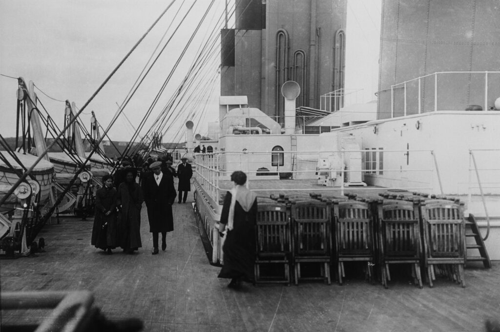
Titanic Tours: Titanic’s Decks Most Titanic enthusiasts and historians dream of the chance to walk the decks of the ship and experience her in all her glory. We imagine ourselves strolling the promenade deck or examining the boats on the boat deck. This week, we’ll explore how those decks were made. A few weeks ago, we looked at Titanic’s frames and how they formed the steel skeleton of the ship, rising vertically to form what we think of as ribs. To these frames and the beams emanating from them, the decks would be attached. It’s important to note that Titanic’s decks were not “flat” by any stretch. They would have had a gentle transverse rise in the center of about three inches. It would have been hardly noticeable to passengers unless they were paying close attention, but it was designed to ensure that water that accumulated due to wave action could easily find it’s way to the sides of the ship and then out the scuppers cut into the hull bulwarks. This rise, called “camber” was present on all of Titanic’s decks. The decks themselves were constructed of steel plates and were assembled along the same lines as the hull, with the in and out system of overlapping edges present. As discussed last week, expansion joints were incorporated into the decks above B deck to allow the rigid steel movement in a seaway. In this way, the decks could flex where needed, but otherwise they were as rigid as the hull itself, while not providing additional strength to the hull girder. The more visible and better-known element of the decks was the wooden sheathing over the steel plates. The wooden planking on her decks was not just decorative, it served a number of important purposes. As steel decks would warm in the sun or chill in the cold, the wood provided a more-uniform temperature for places where passengers and crew would walk regularly. Since wood does not transmit temperature changes, it also helped maintain the temperature inside the ship. Titanic and her sisters incorporated both pitch pine and yellow pine deck planks. The pitch pine was used in high use/high stress areas only, with the yellow pine everywhere else. Planks were typically three inches thick and five inches wide, varying in length to suit the space, and secured to the steel by heavy iron bolts. Once laid, the planks were caulked to help keep them in place. Inside the ship, wood planking was also used in some spaces, but tiles (both linoleum and ceramic), carpet, and parquet could also be found in various spaces. Ceramic tiles were often used in areas where moisture would often be present (lavatories and the swimming pool, for example),while linoleum was found in many passageways, staterooms, and public spaces. Today, tiles from Titanic’s sister Olympic are highly collectible. Next Week: Titanic’s Deckhouses Written By: Nick DeWitt Photo Credit: Titanic Connections Archive Photo Captions: 1: Passengers walk along the boat deck, where pitch pine planks can be clearly seen 2: The well-known (and now highly collectible) two-color tiles found in many parts of the ship are seen here in Olympic’s first class Smoking Room 3: Octagonal tiles are discernable here lining the deck around Olympic’s swimming pool
Titanic Tours: Titanic’s Expansion Joints
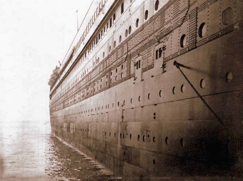
Titanic Tours: Expansion Joints In the nearly four decades since Titanic’s wreck was discovered at the bottom of the Atlantic, there has been a great deal of focus on the way the ship sank and why things happened the way that they did. A great deal of interest has arisen, naturally, around the ship’s breakup. Given the location of the break, a lot of questions have been asked about the ship’s two expansion joints and whether they could have played a role in her breaking in two as she sank. As liners grew in size, expansion joints were inserted to help the vessels survive the potentially strong seas they would face. Ships, particularly on the North Atlantic run, experienced some of the most varied and severe sea conditions in the world. Oftentimes, they would encounter series of waves that caught the hull of the ship in between. If the bow and stern were supported by water by the ship wasn’t supported amidships, she could sag there. If the opposite happened, the ship could “hog,” or bend down at the ends. Without expansion joints, the superstructure of the ships, which was built of lighter plating materials and not designed to withstand heavy stresses, would be prone to cracking or could even fail entirely. Even with expansion joints, the larger liners, including Olympic through her long career, could require servicing of these areas after encountering repeated extreme seas. Olympic and Titanic were fitted with two expansion joints, each starting just above the level of B deck and rising throughout the rest of the ship’s superstructure, allowing it to flex slightly in rough seas. The forward of these two expansion joints was located just abaft of the forward funnel at frame 49F. The after expansion joint was located between the third and fourth funnels at frame 28A. This effectively divided her superstructure, the area above B Deck, into three units. Each joint’s horizontal opening was covered with a brass plate. On the top two decks, a leather strip was also included, the leather opening and closing on the bellows principle as the joint opened or closed at sea. These leather strips were also used on the vertical openings in the superstructure. The coverings, of all types, ensured both watertight integrity, with the leather catching and draining away water it collected, and the safety of passengers. The discovery, in 2006, that Britannic’s expansion joints had a bulb-shaped base (as opposed to the was Olympic’s and Titanic’s joints met at a point), as well as the inclusion of an additional joint amidships, caused many questions to be asked about whether Harland and Wolff felt the joints were a contributing factor in Titanic’s sinking. This can be discounted by the fact that Olympic’s joints were never significantly altered during her more than two decades of service on the Atlantic and also the fact that those joints never failed or were in danger of failing during her long career, including strenuous trooping service in the Great War. The differences in Britannic, from the new shape at the base of the forward joint to the new midships joint, which shifted the after joint to the rear, and even the inclusion of a fourth joint aft where her well deck there was enclosed, can be put down to the fact that the third ship of the trio was significantly different from the first two. With Olympic having experienced some signs of stress in her first year in service (before the loss of her younger sister), it is entirely possibly that Harland and Wolff had already begun rethinking the use of expansion joints before the tragedy. In any case, the idea that Titanic’s expansion joints somehow contributed to her hull’s failure also founders on the knowledge that these joints only went as far down as B deck and were designed to allow the lighter superstructure to flex. They did not compromise the integrity of her box girder hull design, coming to an end point above the strength deck. It is important to think about what else is located in vicinity of the break, namely the large open space of the reciprocating engine room, and also to acknowledge that Titanic’s design, in modern tests, exceeded the maximum levels of stress that could reasonably be expected. As with so much else with the ship’s loss, a set of circumstances far beyond anything that could have been predicted led to a very tragic outcome. Next Week: Titanic’s Decks and Deckhouses Written By: Nick DeWitt Photo Credit: Titanic Connections Archive A view of Olympic during her fitting out. To the left, the third funnel can be glimpsed. On the right side, the lines running through the deck between the deckhouses are the ship’s after expansion joint (at frame 28A), the brass plate clearly visible in the middle of the joint. On the far bulwark, the vertical leather stripping can also be seen. The plans for Olympic and Titanic’s expansion joints, showing the various aspects of their construction and how they functioned. Previous Next
Design D: The Interior
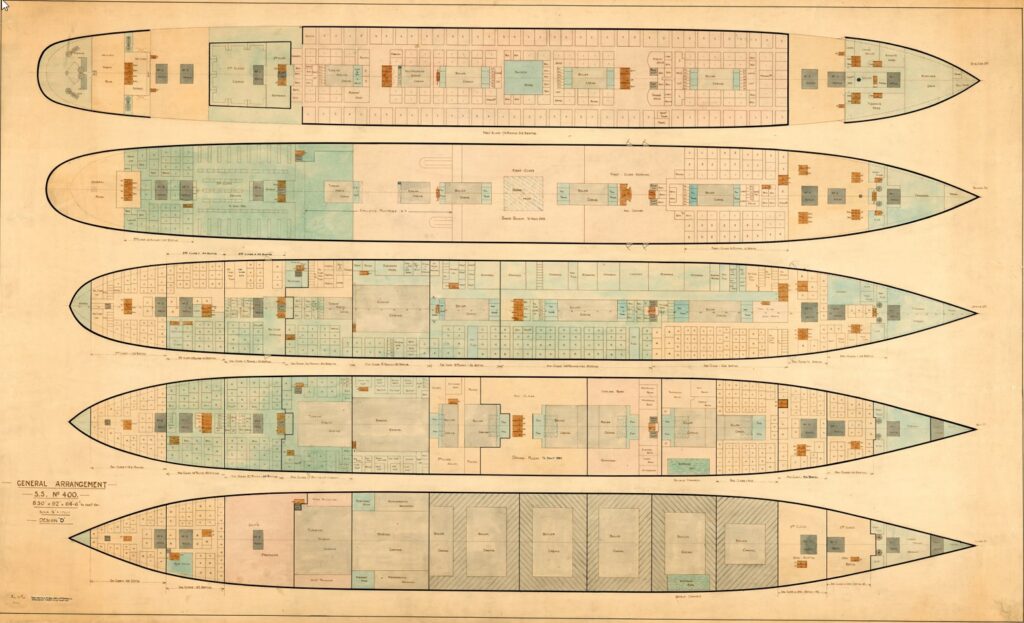
Titanic Design D: The Interior Did You Know… …that the interior arrangements in the original design for the Olympic-class ships, known as Design D, are just as varied from what was actually built as the external features we discussed in last week’s post? While the lack of a second mast after and a clustering of the ship’s lifeboats along the after boat deck is certainly a visual departure from the Olympic-class liners we’ve come to know and love, passengers stepping aboard would have found the ships to be very different from the ones that eventually set sail in 1911 and 1912. The most noticeable change would be the grand staircases. In both cases, these would have been more typical and rectangular staircases, similar to what we eventually saw in the Olympic-class’ second class spaces. The elevators, or lifts, would not have been located behind the forward grant staircase, but across from the front of the staircases, with a port and starboard elevator rather than a stand of three lifts. A deck would be very similar in layout to what was eventually built, with the Lounge, Smoking Room, Palm Court, and Reading and Writing Room all located in the same spots and with the same general shape. The aft part of the deck would have been smaller without the protrusion for the mast and also seems to be lacking the large cargo cranes, although it’s unclear if these are just omitted in the drawings, as no cranes appear around any hatches. B deck is very similar in design to the Olympic, with a large promenade space along the sides, but two major differences jump out from the drawing. The first is the lack of an A La Carte Restaurant for first class passengers. Instead, the second class smoking room is much enlarged. The more interesting change, however, comes near amidships, where there is a large space noted to be for a dome over the first class Dining Saloon. Olympic and her sisters would have a single-deck space for first class to dine, a radical departure from the grand, multi-deck spaces on other large liners built in England, Germany, and France. Design D, at least in this respect, places the Olympic-class ships closer to their contemporaries. This space is also marked on the plans for C deck. In both cases, this unbuilt dome would have taken up space later used for cabins and other small rooms. C deck is otherwise a near-mirror for the as-built ships, with only minor changes to the number and shape of rooms. D deck, however, is radically changed. The first class entrance and a second lounge space, what was later termed the reception room, is much larger in the original plans. Ironically, the final reception room was considered to be a bit too small. The major change here is that the entrances are not walled off from the staircase landing, providing a more open space without altering the rest of the floor plan. Interestingly, the otherwise typical staircase fans out on D deck into a shape more recognizable to our eyes. It is interesting to ponder what Design D’s Dining Saloon would have looked like with a two-deck dome space in its center. The third class General Room is housed here near the stern, as opposed to opposite the Smoking Room for that class on C deck in the final design. E deck holds little more than a few minor alterations, but F deck provides yet another surprise. The Gymnasium, to eventually be found on the starboard side of the Boat Deck, is on the starboard side here instead. The Turkish Bath area is shifted to the port side, where spaces for stewards were eventually located. While this seems a jarring change to us now, this may have been a more practical one in 1912. Olympic and Titanic did not have spaces for changing attached to their Gymnasium. Passengers using the facility would’ve had to pass through public spaces to change, something that would’ve been odd for the times. Most ships that housed a gymnasium at the time had it in the same location as found in Design D. G Deck holds our final major surprises, with the omission of a Squash Court forward being among two notable changes. The other is the location of the ship’s Post Office. Unlike in the final design, where the Post Office was forward on G Deck, Design D places it on the starboard side, but far aft in an area eventually occupied by third class berths. This would certainly have changed some of the story on the night of 14 April 1912, when the mail clerks were among the first to report that their area of the ship was flooding fast. Design D, like most initial designs for any structure, shows a lot of similarities with the what was finally built several years later, but it also shows some interesting differences, some that would’ve advanced beyond typical designs of the time and some which would’ve been a step backward from what eventually became Olympic and Titanic. It is fascinating to look at these designs today and imagine just how different these ships could’ve been. Written By: Nick DeWitt Photo Credit: Titanic Connections Archive Previous Next
Titanic Tours: The Framing of the Titanic
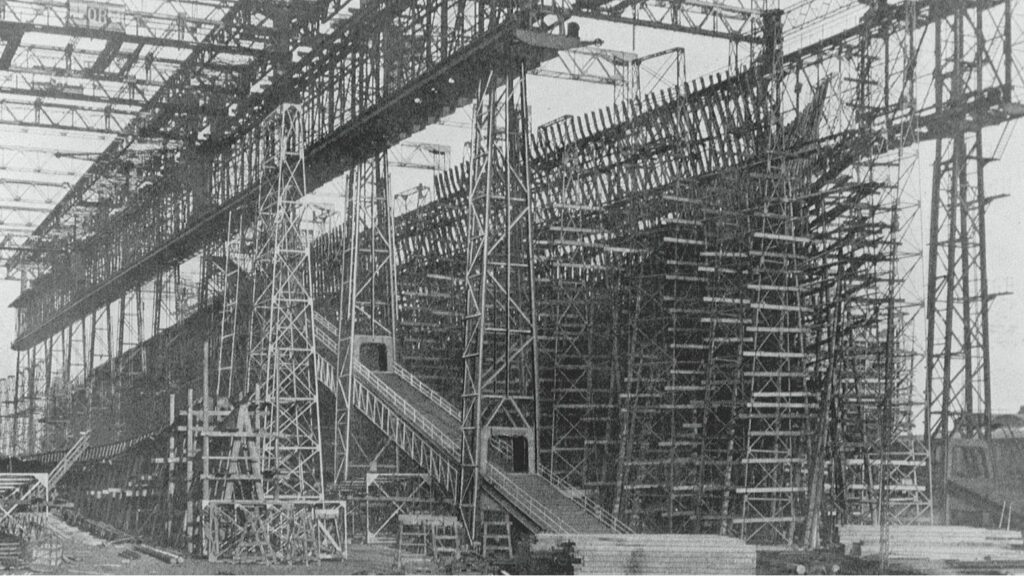
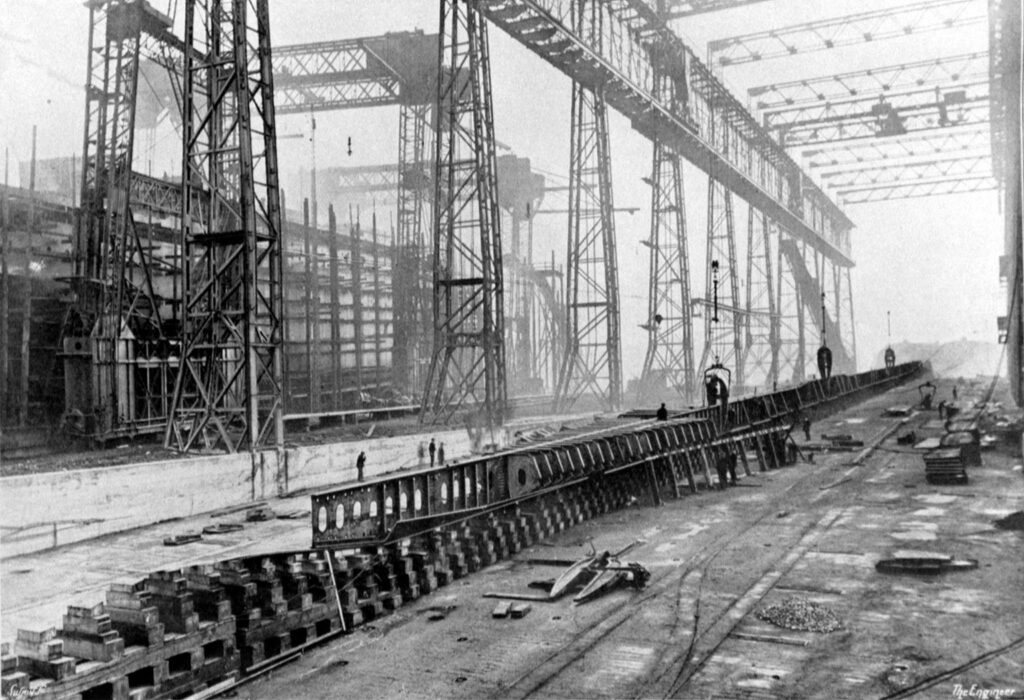
Titanic Tours: The Framing of the Titanic Last week, we looked at the visible outer part of the ship’s hull, her plating, castings, forgings, and rivets. We also discussed the way in which the individual plates were assembled. The plates, which formed Titanic’s outer skin, would not, however, have anything to attach to if not for the frames. The frames inside a ship’s hull are not visible in exterior photographs and are only somewhat evident in photographs of the interior. They are like the skeleton in a human body, giving a ship its overall shape and also providing strength and internal structure. Ships are divided by transverse frames spaced at intervals from the stem to the stern. While various numbering schemes for frames can be used, Titanic’s frames were numbered from amidships, with the exact middle frame left unnumbered. Each frame radiating from that was numbered sequentially and denoted as either forward (“F”) or aft (“A”) of the midship frame. Thus, the frame directly forward of amidships was “1F” and the one directly aft was “1A.” At the forward perpendicular, the forward-most frame was 156F. At the front of the sternpost was the aftmost frame, number 148A. The transverse frames were spaced differently in different areas, closer together at the bow (as close as 24 inches) and stern (as close as 27 inches) and further apart amidships (up to 36 inches). The closer spacing was due to the ship’s experiencing higher stresses on the hull at the ends. The frames ran from the tank top above the cellular double bottom (which formed their floor) to B deck, including the forecastle and poop decks. This formed the “box girder” of the ship’s hull, a hull form that proved incredibly strong and resistant to the high stresses of the North Atlantic routes. Each frame was composed initially of a straight steel bar that was then bent to the needed shape. The frames, once attached to the ship’s bottom, were joined by beams at each deck level. These were supported vertically by pillars and longitudinally by girders. Stringer plates were also fitted in specific areas to increase strength, with these running horizontally along the frames where the vertical distance between beams was larger (as in the holds, boiler rooms, and engine spaces). Stringers were also fitted at B-deck level for added strength. Framing of the ship would be completed before plating, as the plates would attach to the frames. Frames would subsequently be used to identify locations on the ship (you can often see a frame referenced in studies of the damage by the iceberg, for example). With the beams and pillars giving a ship the basics of its internal form, rooms and interior spaces could be constructed around them when the time came. Next Week: Making Titanic Watertight Written By: Nick DeWitt Photo Credit: Titanic Connections Archive Olympic’s framing is nearly complete in this image, showing the skeletal structure which gives the ship her overall form. This looks at her from her starboard bow, with the beginnings of Titanic just visible on the left of the frame. A close-up view of Titanic’s framing in progress
Titanic Tours: The Hull
Titanic Tours: The Hull This week, we’ve arrived at something that everyone will be able to recognize right away: Titanic’s steel hull. The construction of her hull is quite intricate, which becomes evident when one closely analyzes photographs of it. From the thousands of rivet heads to the rows of plating defined by their slight overlap, the hull is a study in the shipbuilding techniques of the early 1900s. Let’s start with the basic materials that made up the hull. Titanic’s hull was made up of individual plates, each of them averaging 30 feet in length and six feet in width, with a thickness averaging one inch, but thinning toward the bow and stern ends. The largest plates were 36 feet in length. Each plate weighed in around four tons. The plates were of mild steel, rolled in a low-speed mill, and were of extremely high quality for the time. The plates were held together by rivets, about three million of which were used in her overall construction. Shipbuilder magazine’s special number on Olympic and Titanic notes that over 500,000 of these rivets were located in the double bottom we discussed last week. The rivets were of wrought iron and of various sizes up to one and a quarter inches in diameter. The rivets along the sides of the hull, where the plates were relatively flat and the holes easy to access, were driven hydraulically. The ones at the ends and at the turns in the hull where hydraulic riveting wasn’t possible were driven by hand-hammering. The rivets were placed while still white hot, allowing them to expand into the hole as they cooled. Other parts of the hull, such as the propeller shafts and rudder post, were made by the process of forging, or hammering or pressing a heated steel into a required form. Likewise, the ship’s rudder, stem, and stern frame, among other components, were made by casting, where molten steel was poured into a cast, or pattern. Both casting and forging were used for special shapes that couldn’t be rolled in a mill as the plates were, and also to create parts that were required to be particularly strong and stand up to stress. Two methods were used to assemble the hull, giving its distinct pattern. The lower part of the hull was built with the “clinker” method, where each row, or strake, was placed outboard and overlapping with the previous and lower one. Once the turn of the ship’s bilge was passed and the hull proceeded upward to form the sides of the ship, the method switched to an “in-and-out” one, where an inner strake was positioned against the individual frames and alternated with an outer strake that overlapped the adjacent inner strakes. While much has been made of the strength (or lack thereof) of Titanic’s hull and rivets, it’s important to note that Titanic’s construction used the best methods and materials available at the time. As Harland and Wolff built ships for White Star on a cost-plus basis, there was also no incentive or need to cut corners to meet a budget. Finally, as Titanic sank, her hull was subjected to extraordinary stresses and not only stood up beyond her design specifications and the expectations of her builders, many of her rivets and hull plates remain fully in place today on the ocean floor. The hull was formed around a series of frames. Next week, we’ll take a look at how the framing was completed. Next Week: Titanic’s Frames Written By: Nick DeWitt A close-up of Titanic’s side, showing in great detail both visible riveting (on C and D deck) and the “in-and-out” method of overlapping the plates on the side of the hull The workshop at Harland & Wolff where castings were made. Here, you can see forms for some of the propeller blades, including a workman finishing a blade on the right.
A Titanic Tour: From the Keel Plates up
A Titanic Tour: From the Keel Plates up On 31 March, 1909, the first plates of Titanic’s keel were laid in Slipway No. 3 at Harland & Wolff in Belfast. The keel-laying is the first event in the life of a new ship. Titanic’s keel plates are described in the magisterial “Titanic: The Ship Magnificent” as follows: “Flat-plate design, formed by a single thickness of plating 30/20 inch thick and reducing to 24/20 inch thick toward the ends. The keel plate was 52 inches wide at its broadest point.” A “slab bar” of 19 1/2 inches by 3 inches provided extra strength below this plate. This also, as the authors note, protected the keel plates from damage via grounding and dry-docking. The “vertical keel,” which rose from this line of plate, helped form the central part of the ship’s double bottom and created what is commonly known as the ship’s “backbone.” This spine varied in thickness from 63 inches to 75 inches below Titanic’s gargantuan reciprocating engines. Looking at the ship, the keel is discernible from the rest of the bottom of the hull as a wide strip of riveted plate running down the center line. Initially resting on wooden blocks, like those that can still be seen today in the Thompson Graving Dock in Belfast, the keel would eventually be attached to the “floors,” which formed the outer skin of Titanic’s bottom and the lower plating for her cellular double bottom. Growing first outward and then upward, the hull would eventually radiate out from her keel and form the “box girder” of her hull, an incredibly strong and resilient design that had become common during the 19th century move to iron and steel construction. While Titanic’s keel is not the most glamorous part of her construction, it is one of the most important individual pieces of the ship. Given the immense hogging stresses that the hull was placed under as she sank upright (rather than the more common capsizing that usually is present during a sinking), the strength of her keel determined how long her hull maintained its integrity. With Titanic surpassing even Thomas Andrews’ on-site calculations about the time she could remain afloat, her backbone can be said to have been incredibly resilient. It is ironic that Titanic has been derided in some circles as a “weak” or “poorly constructed” ship. Nothing could be further from the truth. Titanic’s keel was perhaps the last part of the ship to part during her breakup. Two surviving sections of her double bottom were located in the mid-2000s and have since been extensively studied. The keel bar itself can be seen in photos of the sections. Next Week: The Double Bottom Written By: Nick DeWitt Photo Credit: Titanic Connections Archive
