
Titanic Tours – The Bridge
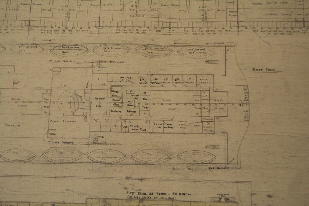
Titanic Tours – The Bridge A Titanic Connections Feature by Nicholas Dewitt The General Arrangement (GA) plans for the bridge area. These would be similar for both Olympic and Titanic, but Olympic was initially equipped with a curved-front Wheelhouse. Titanic’s was flat-fronted as presented here. The brain of any vessel at sea is her bridge. In the case of Titanic, the bridge is where some of the most consequential actions of 14 April 1912 occurred. This week, we’re heading there to take a look at this important space. Before we begin, a little historical note on the term “bridge.” Sailing vessels did not have a bridge, being instead navigated and commanded from the quarterdeck where the ship’s wheel could be found. But with the arrival of steam power and the equipping of ships with paddle boxes on their sides, the ship’s engineers needed a way to easily get from one paddle box to another and inspect the machinery. This took the form of a raised platform that stretched between the two boxes, forming a literal bridge. When paddles disappeared in favor of the screw propeller, the bridge stayed and became home to the ship’s command and navigating instruments. On the Olympic-class liners, as with other liners of the era, the bridge was located forward atop the superstructure. Denoted by a series of nine rectangular windows at the front center of the boat deck, the bridge encompassed a Navigating Bridge just behind the windows, an enclosed Wheelhouse situated behind that space, and encompassed the swept-back wings on either side that ended in a covered “cab” where officers could observe goings on below and to either side. We will explore all of these spaces in today’s tour. Connected to the Wheelhouse were a Chart Room, a Navigating Room, and quarters for a harbor pilot. We will explore these rooms at a later date. Navigating Bridge Each space above had a specific function to perform. Let’s begin with the Navigating Bridge. This space contained five order telegraphs, a wheel, and compass binnacle. There were also two small fold-down tables on either side wall that could be used for charts. While the wheel here was only manned when traveling near shore, the five telegraphs could and would be utilized to communicate with the various engine spaces throughout a voyage. The two outermost telegraphs were connected to the engine room to transmit orders for the speed of the ship. Each of the drums had an indicator for dead slow, slow, half astern, full astern, dead slow, slow, half ahead, full ahead, stop, stand by astern, and stand by ahead. The port handle of these telegraphs would transmit orders for the port engine and the starboard handle would do the same for the starboard engine. These two telegraphs were also connected to one another, so orders need only be “rung down” on one of the telegraphs. A third engine order telegraph was located directly to port of the wheel. This was the emergency telegraph. It had an independent connection to the engine room in case of the failure of the pair of main engine order telegraphs, but was otherwise the same in function. The two remaining telegraphs were for use when the ship was being docked or was near shore. These communicated with the Docking Bridge located on the poop. One was similar to the three engine order telegraphs, but would relay those commands to the Navigating Bridge from the Docking Bridge. The other had a dual set of commands on the side dials, one inner and one outer. Communicating both ways, the Navigating Bridge could send docking commands such as “Let Go Tug” or “Slack Away Stbd.” The Docking Bridge could also indicate information like “All Clear Stbd” or “Not Clear Stbd” to the Navigating Bridge. At the center of the Navigating Bridge stood the wheel and compass binnacle. The teak binnacle contained a 10” Kelvin-White compass. This was one of four main compasses aboard the Olympic-class ships, with the others being located in the Wheelhouse, a midships Compass Platform, and on the Docking Bridge. The compass inside the binnacle would have been lighted for easy viewing at night. Behind the compass binnacle was the ship’s wheel, one of three that could be used to steer the ship. This wheel, made of teak and measuring 3’ 9” in diameter, was mounted on a 34” high brass pedestal. This wheel was manned only when the ship was close to shore, but was connected to the telemotor in the Wheelhouse, which then connected it to the steering gear under the poop. The Navigating Bridge was fronted by nine large windows, with one of the ship’s bells mounted outside and above the center window. Two more windows opened out from the sides of the space, in line with the main engine order telegraphs. The General Arrangement (GA) plans for the bridge area. These would be similar for both Olympic and Titanic, but Olympic was initially equipped with a curved-front Wheelhouse. Titanic’s was flat-fronted as presented here. BRIDGE WINGS Accessed from the open sides of the Navigating Bridge were the two bridge wings, each with a steel bulwark swept back toward an overhanging bridge wing cab with windows on three sides. This area would be used for observation by officers on watch, providing an unobstructed view forward, to either side, and, thanks to the cab extending slightly over the side, downward to the sea. Immediately outside of the Navigating Bridge, nestled in the space where the bulwark met with the walls of the bridge, a pillar stood for use in mounting a pelorus. Also known as a “dumb compass,” a pelorus was used at times to take bearings. The pillar allowed it to be mounted above the bulwark for this purpose. Also of use in navigating the ship were the wing cabs, each of which was equipped with the sidelights used in navigation (red to port and green to starboard). These were designed so that they could each be
Titanic Tours – The Funnels
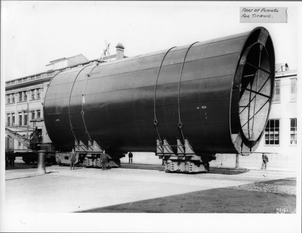
Titanic Tours – The Funnels Photographs of a profusion of colorful funnels poking above the piers of New York Harbor are some of the most well-known images of the era of the luxury liner. A ship’s funnels, while an extremely functional necessity in most cases, can also become iconic, immortalized as baubles for passengers to purchase. Today, these are highly sought-after collectibles. Funnels are not a purely visual element of a ship, however. While the look and number of funnels can sometimes be put down to a stylistic choice, funnels came into existence and have remained a key component of non-nuclear ships for an important reason: to vent the gasses, cinders, and smoke generated by a ship’s engines up and away from the decks and the passengers and crew who roamed them. The history of liners is peppered with examples of ships, such as Norddeutscher Lloyd’s Bremen and Europa, that had their funnels made taller when the too-squat models initially fitted failed to do this basic task well. Titanic, as readers probably are aware, had four funnels atop her superstructure. Each of these were oval shaped, measuring 24’ 6” in diameter running fore to aft and 19’ in diameter running port to starboard. While they were level with one another at the top, the uneven height of the deckhouses above the boat deck meant that they rose to various heights, from 70’ for the first funnel to 73’ for the fourth to 74’ for the second and third funnels. The funnels were raked gracefully back, both for style and function, and, unlike the Cunarders Lusitania and Mauretania, spaced evenly and widely along the superstructure. This gave the Olympic-class ships a more yacht-like, graceful appearance than the greyhound racer profiles of the Cunarders. The funnels were also where the ship’s whistles were located, mounted on the forward side of each funnel. These were reached by a ladder that ran up the front of the funnel. Only the whistles on the first and second funnels were operational, those on the third and fourth funnels being purely decorative to ensure all four funnels looked uniform. Copper steam escape pipes ran up the fronts and backs of each funnel as well. It was from these pipes on the night of 14 April 1912 that steam loudly escaped as the liner came to her final stop, temporarily deafening those on deck. Funnel colors were important for identifying a ship with her company. As the shipping world expanded, each line developed their own color scheme. The White Star Line had adopted an 18’ tall black band at the top with the rest of the funnel painted in a color known as “White Star Buff.” The exact shade of this color will probably never be known for certain, and is believed to have varied somewhat from painting to painting and throughout the company’s existence. While model makers and artists make their own choice as to how best to represent this color in their creations, the easiest way to describe the color is as a pale orange-yellow. Researcher Robert Read has done an authoritative article on the likely formulations of this color which is linked below for those interested. The exterior, however, is only a small piece of the story here. The funnels each served various functions for the ship, entailing a varied structure inside each. The exterior tube that can be seen is actually fitted over and connected to an internal tube. This tube was the “working” part of the funnel, designed to conform to the job it was expected to perform. The first three funnels performed the expected function of funnels everywhere: venting the exhaust gasses and cinders from the ship’s six boiler rooms, with each funnel servicing two of these spaces. Each of these sets of boiler rooms comprised a different amount of fire grate area (the space in which the coal was actually burned to power the ship), so each funnel had a slightly different design. Each boiler’s uptakes stretched toward the center of the ship, where they gradually combined to be vented up through that funnel. The ship’s fourth funnel has been the source of much confusion over the years. While it is true that only the first three funnels were required for the Olympic-class liners to operate, this fourth iteration did serve in important ways. From a decorative perspective, the fourth funnel conveyed the idea of power and size to a traveling public that had become accustomed to the biggest and fastest ships sporting four funnels. It also allowed for a balanced look, with four funnels spacing evenly along the ship’s profile in a way that would not have been possible with just three. If it had stopped there, perhaps the fourth funnel could be put down as a true “dummy.” It could be considered as little more than an ornament added for aesthetic reasons only. This funnel, however, had a functional purpose as well. While not required for the ship’s boiler rooms, the fourth funnel provided ventilation for exhaust from the ship’s galley spaces, the extra tariff restaurant on B deck, the first class Smoking Room, the Turbine Engine Room, and various other spaces throughout the ship. While these spaces could possibly have been ventilated through other methods, being able to combine them into a funnel was much more effective. Each funnel was held in place by 12 stays or shrouds, each measuring 4” in circumference and with six located on each side of the funnel. These were secured at the base of the black-painted part of the funnel at the top and to various pad eyes on the deck at the bottom. Further Reading: Robert Read’s research on White Star Buff can be found here: http://www.titanic-cad-plans.com/whitestarbuff.pdf Content by: Nick Dewitt Funnel Installation This photograph of one of Titanic’s funnels before installation shows the way in which the funnel structure was subdivided and supported. Olympic’s Boat Deck This photograph from Olympic shows how the shrouds attached to both the upper
