
Titanic Tours: Making Titanic Watertight
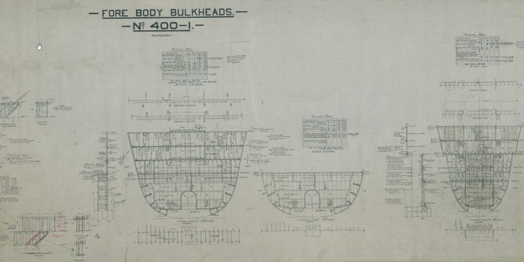
Titanic Tours: Making Titanic Watertight One of the much-ballyhooed features of the Olympic-class liners was their safety features. It would be these safety features, including her watertight doors and subdivision, that would cause the trade publication Shipbuilder, in their 1911 special number, to declare Olympic and Titanic “practically unsinkable.” Surviving a collision at sea was seldom a guarantee, but ships built before Titanic, in some cases many years before, had survived collisions with other ships and even with icebergs. Sinkings, however, were not uncommon in such incidents, with the RMS Republic in 1907 and the RMS Empress of Ireland in 1914 showing that collision damage much less widespread than on Titanic could cause a vessel to founder. Still, despite the accident to Titanic on her maiden voyage, and the later loss of her sister Britannic during World War I, the Olympic-class ships were designed and built with a high degree of safety features. Chief among these features was the cellular double bottom we’ve already discussed in Part 1 of this series. The double bottom formed an inner skin along the vulnerable bottom of the ship. If one of these ships ran over a submerged wreck or rock, it may puncture the outer skin, but would potentially leave the inner skin unscathed, allowing very minimal flooding to occur and permitting the ship to continue with her voyage. Titanic also had watertight bulkheads that divided the lower decks of the ship. Fifteen transverse bulkheads, running from one side to the other, created sixteen watertight compartments. The largest of these would be the space reserved for the ship’s enormous reciprocating engines. Others were of varying sizes, with the bulkheads also not proceeding in a straight vertical line. These bulkheads were lettered from the bow beginning with A and ending with P, omitting the letter I. Each bulkhead rose from the top of the double bottom (known as the Tank Top) as high as either the Upper Deck (E Deck) or the Saloon Deck (D Deck) and remained watertight to that height. The decks themselves were, for the most part, not watertight, lending to the more modern descriptions of the ship’s subdivision as similar to that of an ice cube tray. These bulkheads, pierced by watertight doors that we shall examine in a moment, gave the liners a high degree of survivability in a collision. One of the worst mishaps that could occur at sea was a collision with another vessel that opened two adjoining compartments to the sea. The Olympic-class ships could survive such a scenario. They could also survive an accident that damaged any three of the first five compartments or even the first four compartments from the bow. Unfortunately for Titanic, her damage just exceeded these possibilities, dooming her. A side-swipe collision opening five or six compartments was not a common or likely scenario, so it was believed that these new ships could survive virtually any mishap that would befall them. Most of these bulkheads (excluding E, F, G, H, and J) had watertight access doors built into their structure. When closed, the bulkhead was watertight. At the level of the Tank Top (the floor of the boiler rooms, coal bunkers, and engine spaces), these doors were of the vertical-sliding variety we are familiar with from films and photographs. These doors were more narrow aft of the boiler rooms, the wider doors in the boiler rooms allowing for the transportation of coal from the bunkers in wheelbarrows. The doors were each held open using an electronic clutch that could be released locally or remotely. If released, the doors would drop quickly into the closed position and thus seal the bulkhead. Each door also was equipped with a float system that would automatically close the door if water rose to 1 ½ to two feet above the tank top. Once closed, the only escape from that compartment would be up vertical escape ladders. These variously led to E Deck, where Scotland Road was located, or up to the Boat Deck. Above the boiler and engine spaces on E Deck and D Deck, the bulkheads were pierced by horizontal-sliding watertight doors. These had a similar look and construction, but operated on a rack and pinion system that would press the door firmly against the bulkhead once closed. These doors could be closed locally from either the same deck or from the deck above using hand cranks. Finally, the liners were equipped with several watertight doors on hinges, which operated the same as a standard door, with a rubber gasket around the rim. These could be sealed by pulling the door shut and turning several “dogs” to firmly seal the gasket to the frame. After the sinking, several design changes were made to both the building Britannic and, during her next overhaul, the Olympic. These would expand the two ships’ double skin from the bottom up the sides, extend some of the watertight bulkheads to B Deck, and provide a panel on the ship’s bridge that showed the status of the watertight doors. This panel is erroneously depicted as being aboard Titanic in most films, but it was not a part of her design. Other smaller changes would also be made, and together these would allow the Olympic and Britannic to survive a Titanic-style accident. Each vessel would now be able to float with her first six compartments opened to the sea. Unfortunately, despite these design changes, Britannic would succumb to a mine in 1916 while serving as a hospital ship. Next Week: Titanic’s Expansion Joints Written By: Nick DeWitt Previous Next A look at the bulkhead design from a bow-on perspective, showing the overall shape of the bulkheads and the ways in which various doors pierced them at each deck. Photo: Titanic Connections Archive Previous Next The starboard elevation plan used at the British Titanic Enquiry in the summer of 1912, showing each watertight bulkhead labeled below the hull. Photo: Titanic
Did You Know… All About Titanic’s Design “D”
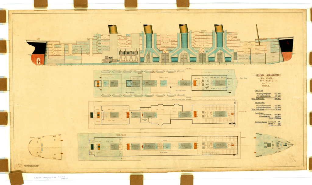
The Intended Exterior of Design “D” For the Olympic Class Did You Know… …that the original design accepted for the Olympic and Titanic, known as “Design D,” had a number of major differences from the two ships that were eventually launched in Belfast? While there are no known drawings of what presumably would be called Designs A, B, and C, we do have the existing Design D drawings, which are the ones upon which Harland and Wolff would have presented to the White Star Line when the two agreed upon the building of the two ships (with the possibility of a third to be completed later). The presumption has always been that the three “missing” designs would be scaled-up versions of the Big Four liners, particularly Adriatic, the last of that grouping. We can only wonder at what the first conceptions of White Star’s new mammoths might have been. Design D, however, shows not so much a scaled-up Adriatic but a design that is in some ways a radical departure from that of ships of the time and in others very reminiscent of other contemporaneous designs. Perhaps that most noticeable thing about Design D, given how important they would later be to Titanic, are the ship’s lifeboats. The design shows 14 full-size lifeboats with two smaller cutters at the front. This, at least, matches the initial compliment on Olympic and Titanic save for the additional four Engelhardt collapsible boats. All 16 boats, however, are placed aft on the boat deck, with the cutters being just abaft the second funnel and each followed by seven evenly-spaced regulation lifeboats. This would have drastically changed the appearance of the new ships. While the placement of the lifeboats would’ve been different to our eyes, it would’ve followed the practices seen in the Big Four. Adriatic’s boats were situated after just as Design D shows them for the Olympic-class ships. A more radical change in the design, however, would be the omission of a mainmast. While not necessarily the first thing noticed in the drawings, a closer inspection shows only the foremast. This would have completely altered several aspects of the Olympic-class ships and been a complete departure from contemporary designs of the time. The new Lusitania and Mauretania each had two masts, while the Big Four ships each had four. A single mast would not become vogue until near the end of the ocean liner era in the 1950s and 1960s. Beyond the visual changes, the Olympic-class ships would have had to make alternative arrangements for their wireless aerial, which could no longer be suspended between two masts. It is likely that, as with some later vessels such as the Empress of Britain in the 1930s, that this aerial could have been suspended between two of the funnels. As wireless was still in its infancy in 1907 and 1908 when these designs were coming together, this was likely not a primary concern to Harland and Wolff, but if followed through on, it could’ve had an important impact on the Titanic during her ill-fated maiden voyage. The rest of the outward design, as far as we can tell, is likely to be very similar to what we have come to know. Four buff, black-topped funnels, the graceful counter stern, the classic bow shape, and even the overall shape of the superstructure are all there very close to the way we remember them. There’s no complete exterior drawing to show exactly what she would’ve looked like, but it’s safe to say that she would’ve looked similar on the outside. The one other exception is the center anchor and hawse pipe, which do not make an appearance on either the overhead drawing of the forecastle or the starboard elevation. The compass platform might also have been located elsewhere, as a dome over the first class lounge appears to be in that spot in Design D. Internally, however, the ships would be quite different. Next time, we’ll take a look at the internal differences between Design D and the Olympic-class as they were built. The first page of the original drawings for Design D, showing a starboard elevation and overhead looks at the Boat Deck, A Deck, and B Deck (including the forecastle and poop) Previous Next
Wreck Thursday: Decks of a Legend
Wreck Thursday: The Decks of a Legend One of the oft-overlooked, (and taken for granted) details concerning the wreck of Titanic has been the lack of visible ‘Wood’ on the great liners’ upper decks. The Olympic Class Liners had decking that was comprised of several types of wood, the primary of which was Yellow Pine, the others being Pitch Pine, and of course Teak. Much like all ships of the period (and even those today), the Titanic’s decks were comprised of steel that was “sheathed” with wooden planking. The decking was not just for aesthetics… it also allowed for a level, safe, surface to walk on, provide insulation, and served to protect the bare steel from corrosion caused by the salty Atlantic air & water. The Titanic’s foredeck & Aft Poop Deck were sheathed primarily with pitch pine (a bit more durable than Yellow Pine) and the ever-resilient teak wood, which was used as trim around much of the liners deck hardware. Both the Boat deck and promenade deck were sheathed with yellow pine and teak, the latter of which trimmed many of the bulkheads and roofs along the officer’s quarters and even the forward Bridge. Teak was the most resistant to decay, and by proxy, it would almost assuredly never have to be replaced unless the equipment it shielded was ever replaced or removed. All of the wood on Titanic was fastened to the steel deck by way of fasteners and dowels. The planks themselves were several inches thick (and varied in size & thickness) and were finally sealed with caulking. When the Titanic was first filmed in 1985 & 1986 a review of the footage started a hasty rumor that the Titanic’s decks were totally decayed, leaving only their bare outlines on the riveted steel. A review of the available footage came to the conclusion that much of what was seen was, in fact, “Ridges of caulking” as opposed to physical wood planks. Thus the rumor began that the great liner was simply a metal shell, devoid of all form of woodwork. This idea prevailed until the 1987 French IFREMER expedition sent cameras deeper inside Titanic than had been attempted by Dr. Robert Ballard and his camera ‘Jason Junior’ (J.J.). Subsequent explorations conducted to the wreck of Titanic have proven these rumors to be false, and as we shall now see… much of Titanic’s deck still remains to be seen and examined. Lets take a look for ourselves…. Please see images for additional text and information. Post by: Matthew Smathers Information & Images Courtesy Of:Encyclopedia Titanica,Daniel Klistorner,NOAA,Vasilije Ristovic,Father Browne Collection,CyArk Archive,Titanic: The Ship Magnificent,Bruce Beveridge,Ken Marschall,Mark Draper,Riley Gardner,Woods Hole Oceanographic Institute,Rms Titanic Inc.Storied Treasures Collection, Previous Next
Titanic Tours: The Framing of the Titanic
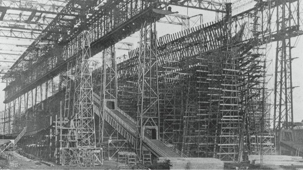
Titanic Tours: The Framing of the Titanic Last week, we looked at the visible outer part of the ship’s hull, her plating, castings, forgings, and rivets. We also discussed the way in which the individual plates were assembled. The plates, which formed Titanic’s outer skin, would not, however, have anything to attach to if not for the frames. The frames inside a ship’s hull are not visible in exterior photographs and are only somewhat evident in photographs of the interior. They are like the skeleton in a human body, giving a ship its overall shape and also providing strength and internal structure. Ships are divided by transverse frames spaced at intervals from the stem to the stern. While various numbering schemes for frames can be used, Titanic’s frames were numbered from amidships, with the exact middle frame left unnumbered. Each frame radiating from that was numbered sequentially and denoted as either forward (“F”) or aft (“A”) of the midship frame. Thus, the frame directly forward of amidships was “1F” and the one directly aft was “1A.” At the forward perpendicular, the forward-most frame was 156F. At the front of the sternpost was the aftmost frame, number 148A. The transverse frames were spaced differently in different areas, closer together at the bow (as close as 24 inches) and stern (as close as 27 inches) and further apart amidships (up to 36 inches). The closer spacing was due to the ship’s experiencing higher stresses on the hull at the ends. The frames ran from the tank top above the cellular double bottom (which formed their floor) to B deck, including the forecastle and poop decks. This formed the “box girder” of the ship’s hull, a hull form that proved incredibly strong and resistant to the high stresses of the North Atlantic routes. Each frame was composed initially of a straight steel bar that was then bent to the needed shape. The frames, once attached to the ship’s bottom, were joined by beams at each deck level. These were supported vertically by pillars and longitudinally by girders. Stringer plates were also fitted in specific areas to increase strength, with these running horizontally along the frames where the vertical distance between beams was larger (as in the holds, boiler rooms, and engine spaces). Stringers were also fitted at B-deck level for added strength. Framing of the ship would be completed before plating, as the plates would attach to the frames. Frames would subsequently be used to identify locations on the ship (you can often see a frame referenced in studies of the damage by the iceberg, for example). With the beams and pillars giving a ship the basics of its internal form, rooms and interior spaces could be constructed around them when the time came. Next Week: Making Titanic Watertight Written By: Nick DeWitt Photo Credit: Titanic Connections Archive Olympic’s framing is nearly complete in this image, showing the skeletal structure which gives the ship her overall form. This looks at her from her starboard bow, with the beginnings of Titanic just visible on the left of the frame. A close-up view of Titanic’s framing in progress
Did You Know… about The Romandisea Titanic
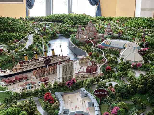
Did You Know… about The Romandisea Titanic? Did You Know… In 2014 Bernard Hill, who played Captain Smith in Titanic (1997) took part in the event announcing a Titanic Attraction at the Romandisea theme park in Sichuan, China? The full-size replica was planned to sit a reservoir within the river Qi complete with an infamous iceberg simulation. The estimated cost of the non-working replica was estimated at about $125 million. Sichuan Seven Energy Investment Group had a keel laying ceremony in November 2016 to commemorate the beginning of what was said to be an 11 month project. The team missed their 2017 completion date and is February 2019 construction was reportedly still underway, with many videos of the construction site with the ship obviously unfinished. By August of 2021 it has been reported that the project was abandoned. Sichuan Seven Energy had reported total assets in the range of $682 million USD, indicating that their focus would be to build a world class modern energy service. In October of 2021 it was reported by Su Shaojun, chairman of the Qixing Energy investment Group Co. LTD., that the project would be another year but he hesitated quite a bit, stating that there would more than likely be many more problems to come. The Tourism Bureau of Sichuan Province also stated, to Surging News, eight months before that the project was operating normally and would be completed in 2022. (https://car.inotgo.com/2021/10/20211023201658892H.html). Su has stated several times that they collected original blueprints for years and were going to make a faithful replica of the great ship within the romantic Mediterranean resort. In 2020 the hull was estimated to be 80% completed but funds for the project rose as construction continued and Su Shaojn joked about needing a money printing machine and they had enough funds to finish only the hull of the project and further funds would have to be raised for the rest. (https://car.inotgo.com/2021/10/20211023201658892H.html) Images: ThePaper.cn reporter Tang YingYing Article: Elena Vukosa Playlist 7 Videos Romandisea Titanic Replica (China) 1:33 A Titanic replica is under construction in China 2:29 China’s Romandisea Titanic: The Progress 1:33 Romandisea Titanic Construction Photos | 24 Pics 4:03 The TITANIC 2 at an Amusement Park in CHINA 4:59 TITANIC 2 CHINA 2022 OFICIAL 2:58 TITANIC 2 CHINA | Romandisea Titanic【Edu8K】 1:49
Wreck Thursday – First Class Cabin D-33 Henry Sleeper Harper
Wreck Thursday – Henry Sleeper Harper’s First Class Cabin D-33 Cabin D-33 was a ‘typical’ 1st Class cabin aboard Titanic, and by ‘typical’ we refer to the fact that, unlike most cabins located on the Titanic’s upper decks, this cabin had bare riveted steel ceilings, and was furnished with a variety of furniture found in several different other staterooms. Despite these details, the 1st Class cabins on D-deck were comfortable and above standards for other competitive Atlantic liners. D-33 was classified as a ‘Three-Berth’ cabin and was occupied by Mr. Henry Sleeper Harper and party. Mr. Harper, the director of the ‘Harper Publishing Company’ (Who most famously published ‘Harpers Weekly’), boarded the Titanic in Cherbourg, France, accompanied by his wife Myra, her dog ‘Sun Yat Sen’ (An award-winning Pekinese), and their Egyptian interpreter Hammad. Comically enough, it seems like all four of them were in D-33, including their dog, who had its own ‘contract ticket’ for the sum of £1 19s (7d). Mr Harper is perhaps one of the most ‘eccentrically fascinating’ passengers aboard the Titanic. He had survived a prior shipboard encounter with an Iceberg about ten years before Titanic, so it is no wonder that when he received word to don lifejackets and head up to the deck that he did so, and yet.. he evidently led his party to the comparative warmth of the ships Gymnasium for awhile before leading his party over to the Starboard wide where they boarded Lifeboat #3. Boat #3 left the ship at 1am with all four of them safely. When dawn rose on the morning of the 15th, he was overheard remarking on how small the Carpathia was compared to Titanic, and then on the way to New York, he encountered a friend amongst the Carpathia’s passengers and seemed keener to speak about his friends ‘Youthful appearance’ as opposed to talking about the disaster he’d just survived. Hidden deep within the heart of Titanic, it was on September 7th, 2001, that bots Jake & Elwood both captured the first images of Henry Sleeper Harper’s cabin since April 15th, 1912. The cabin, though largely destroyed, revealed an incredible discovery… Let’s take a look at the ruins of D-33 and see this discovery for ourselves! **Please See Images for Additional Information** Post by: Matthew Smathers Information & Images Courtesy Of:Encyclopedia Titanica,Daniel Klistorner,CyArk Archive,Titanic: The Ship Magnificent,Bruce Beveridge,Ken Marschall,Peggywirgau.comStoried Treasures Collection,Harland & Wolff Archive, Previous Next
Titanic Tours: The Hull
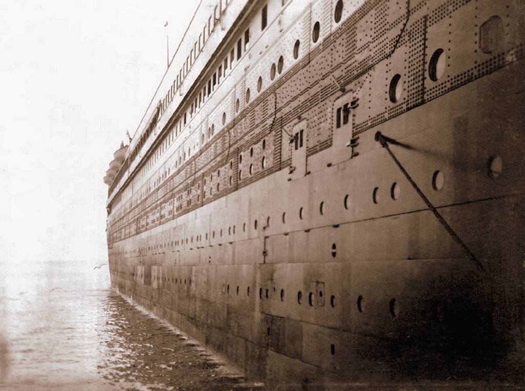
Titanic Tours: The Hull This week, we’ve arrived at something that everyone will be able to recognize right away: Titanic’s steel hull. The construction of her hull is quite intricate, which becomes evident when one closely analyzes photographs of it. From the thousands of rivet heads to the rows of plating defined by their slight overlap, the hull is a study in the shipbuilding techniques of the early 1900s. Let’s start with the basic materials that made up the hull. Titanic’s hull was made up of individual plates, each of them averaging 30 feet in length and six feet in width, with a thickness averaging one inch, but thinning toward the bow and stern ends. The largest plates were 36 feet in length. Each plate weighed in around four tons. The plates were of mild steel, rolled in a low-speed mill, and were of extremely high quality for the time. The plates were held together by rivets, about three million of which were used in her overall construction. Shipbuilder magazine’s special number on Olympic and Titanic notes that over 500,000 of these rivets were located in the double bottom we discussed last week. The rivets were of wrought iron and of various sizes up to one and a quarter inches in diameter. The rivets along the sides of the hull, where the plates were relatively flat and the holes easy to access, were driven hydraulically. The ones at the ends and at the turns in the hull where hydraulic riveting wasn’t possible were driven by hand-hammering. The rivets were placed while still white hot, allowing them to expand into the hole as they cooled. Other parts of the hull, such as the propeller shafts and rudder post, were made by the process of forging, or hammering or pressing a heated steel into a required form. Likewise, the ship’s rudder, stem, and stern frame, among other components, were made by casting, where molten steel was poured into a cast, or pattern. Both casting and forging were used for special shapes that couldn’t be rolled in a mill as the plates were, and also to create parts that were required to be particularly strong and stand up to stress. Two methods were used to assemble the hull, giving its distinct pattern. The lower part of the hull was built with the “clinker” method, where each row, or strake, was placed outboard and overlapping with the previous and lower one. Once the turn of the ship’s bilge was passed and the hull proceeded upward to form the sides of the ship, the method switched to an “in-and-out” one, where an inner strake was positioned against the individual frames and alternated with an outer strake that overlapped the adjacent inner strakes. While much has been made of the strength (or lack thereof) of Titanic’s hull and rivets, it’s important to note that Titanic’s construction used the best methods and materials available at the time. As Harland and Wolff built ships for White Star on a cost-plus basis, there was also no incentive or need to cut corners to meet a budget. Finally, as Titanic sank, her hull was subjected to extraordinary stresses and not only stood up beyond her design specifications and the expectations of her builders, many of her rivets and hull plates remain fully in place today on the ocean floor. The hull was formed around a series of frames. Next week, we’ll take a look at how the framing was completed. Next Week: Titanic’s Frames Written By: Nick DeWitt A close-up of Titanic’s side, showing in great detail both visible riveting (on C and D deck) and the “in-and-out” method of overlapping the plates on the side of the hull The workshop at Harland & Wolff where castings were made. Here, you can see forms for some of the propeller blades, including a workman finishing a blade on the right.
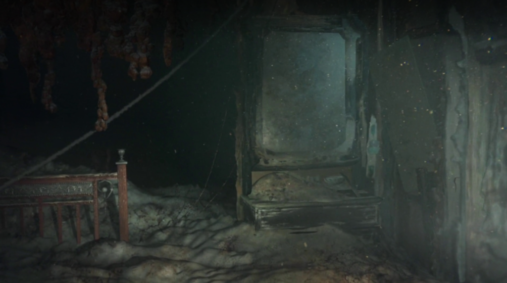
Did you know… Titanic’s Reciprocating engines are still upright on the ocean floor?
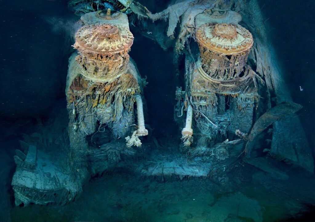
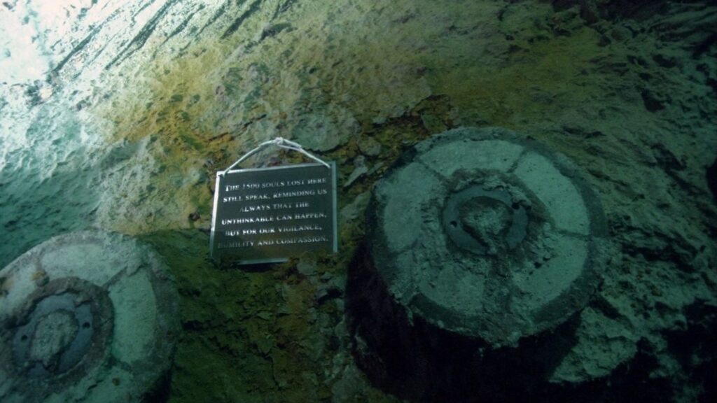
The Titanic had two triple expansion reciprocating engines. The engines were located in the Reciprocating Engine Room on the Orlop Deck, aft of Boiler Room 1. The reciprocating engines drove the port and starboard propellers. Aft of the reciprocating engines was the turbine engines which drove the central propeller.
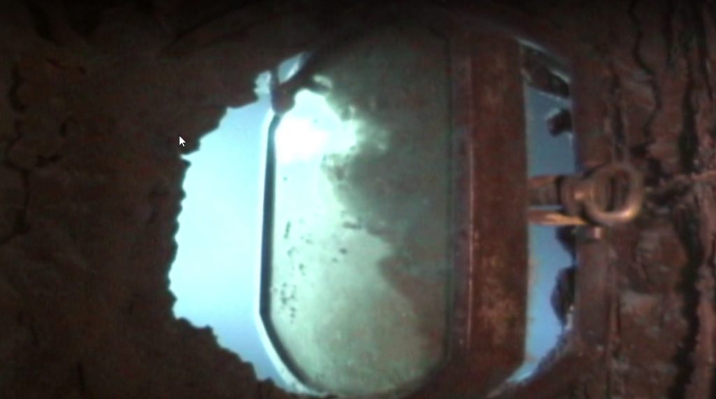
Wreck Thursday – First Class Cabin A-11
Wreck Thursday: First Class Cabin A-11 1ST CLASS CABIN A-11 EDITH RUSSEL Titanic SURVIVOR 1st Class cabin A-11 was located on the Starboard side of A-deck almost directly below the ship’s Bridge. Adjacent to the corridor leading to the forward-facing promenade, it was laid out for single occupancy. Though smaller in size than most of Titanic’s 1st Class staterooms, it was comfortably laid out with a brass framed bed, wardrobe closet, vanity with drawers, a couch, privacy screen over the window, and a washbasin. On the Titanic’s ill-fated first, and last voyage, the cabin was occupied by 1st Class passenger Edith Rosenbaum. A Paris fashion reporter, she had expressed disdain for the ‘stuffiness’ aboard Titanic, as well as her uneasiness about traveling aboard, writing to her secretary just one day onboard she ended her letter by saying “How I wish it were over!” Revealed for the first time in 2001 during the filming of ‘GHOSTS OF THE ABYSS” much of A-11 is crushed and buried in debris, however, there are innumerable traces of Miss Rosenbaum’s cabin which remain intact and readily recognizable as we shall now see… *Please See Images for Additional Information* (Check this link out to hear the actual sound of the MAXIX from Miss Russell’s musical pig https://www.youtube.com/watch?v=PhwZSPmtHNI) Post by: Matthew Smathers Information & Images Courtesy Of: Encyclopedia Titanic, CyArk Archive, Titanic Archive Project, Titanic: The Ship Magnificent, Bruce Beveridge, James Cameron – Lightstorm Entertainment, Ken Marschall, Henry Aldridge & Son Ltd, Storied Treasures Collection, Harland & Wolff Archive,
Titanic Tours: the Double Bottom
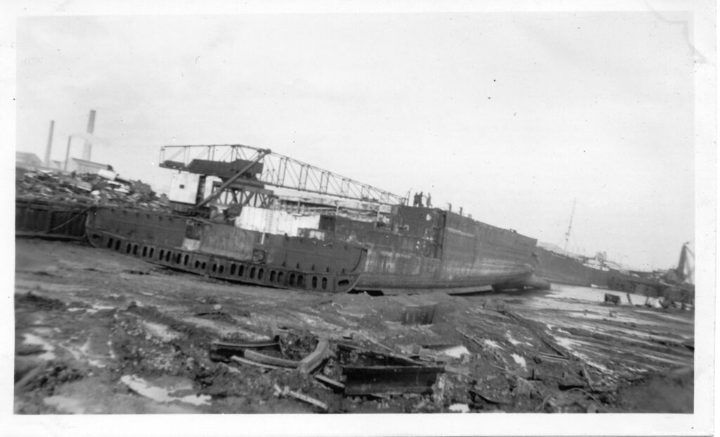
Titanic Tours: the Double Bottom An aerial view of Olympic, looking aft from the bow, showing the subdivision of the double bottom in excellent detail When we discuss Titanic’s watertight subdivision, one of the often-overlooked aspects of her construction is the double bottom. Titanic had what could be called a second or inner skin within the visible exterior hull plates that made up her bottom. As we discussed last week, Titanic had a vertical keel that extended upward from the keel plates themselves. This formed the center point for the double bottom, which took the form of a series of small compartments that formed something of a “honeycomb” at the bottom of the ship under her tank top. Each of these tiny compartments were formed by “floors” at each frame and three longitudinal structures (the keel itself and two margin plates, each located 30’ outboard on either side of the vertical keel). The spaces ranged from 63” to 75” inches in height, being thickest under the heavy reciprocating engines. Each of these “cells” or “tanks” could be utilized for various purposes, from ballast to storage of water. They also were important for Titanic’s stability, preventing water from sloshing around large spaces along the bottom of the ship. Most importantly when it comes to safety features, this cellular bottom and the inner skin it created would help the ship survive grounding collisions where the bottom of the ship was opened to the sea by some obstruction. Rather than a large compartment being opened to the sea and perhaps completely disabling the liner, a small void space would be opened up, giving water much less space to roam free and preventing the ship’s vital components from being damaged or put out of service. As with the keel, Titanic’s double bottom structure can still be viewed today on the two pieces of double bottom that may have formed the final connection between the ship’s bow and stern sections as the liner plunged to the ocean floor. Next Week: Titanic’s Hull Written By: Nick DeWitt Photo Credits: Titanic Connections Archive A view of the Olympic’s double bottom during her scrapping in the mid-1930s from the Titanic Connections Archive
